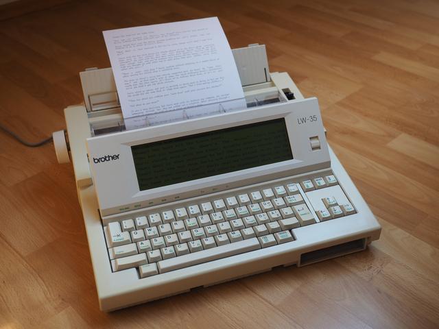
Brother LW-35 Typewriter Modernization | | Saturday, June 6th 2020, 18:06 |
-- Now that's my definition of building a computer!
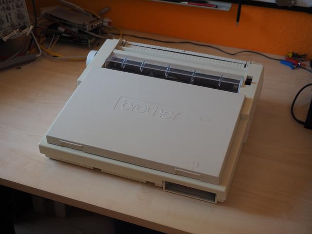
Do you still remember the old electronic typewriters from the nineties? Many of the later machines were already pretty much full-fledged computers, just with a word processor as the operating system. One of these typewriters is the Brother LW-35 released in Europe. I still had one of these lying around; Great keyboard, a fun daisy wheel printer, and a 14 line display for distraction free writing. It even had a floppy drive for data exchange. So in summary, a pretty cool device.
But there were a few problems with it. First of all, the floppy drive stopped working reliably. And secondly, on the days the floppy drive decided to work, it was still a floppy drive. Not exactly the most convenient way to store and transfer data these days, although I'm sure some of you will disagree. Also, the typewriter used its own file format, which needed to be converted on the device itself before it could be read in a DOS or UNIX environment. This may be OK if you're writing a longer document, and only write it on that machine. But as someone who constantly changes the machine they type on, it's not practical.
Yet, even with these problems, I just didn't have the heart to throw it out.
So what can we do about it? Upgrade it!
In this post, I will show you how I converted my old LW-35 typewriter into a modern computer while keeping all the good features of the old machine.
Overview
The whole project took quite a while of on and off work to complete, but in today I will focus on the finished product. If you are interested in the build process, I have a multi-part vlog series [1] about this linked below.
So let's start by taking a look at the high-level specs of the completed system.
- Computer: Orange Pi PC SBC (1.2 GHz Quad-core, 1 GB RAM, 64 GB SD card, 3x USB 2.0, 100M Ethernet)
- Display: Original backlit 480x128 monochrome dot-matrix LCD
- Keyboard: Original German layout keyboard
- Printer: Original daisy wheel printer with three typefaces and correction tape
But What About Software?
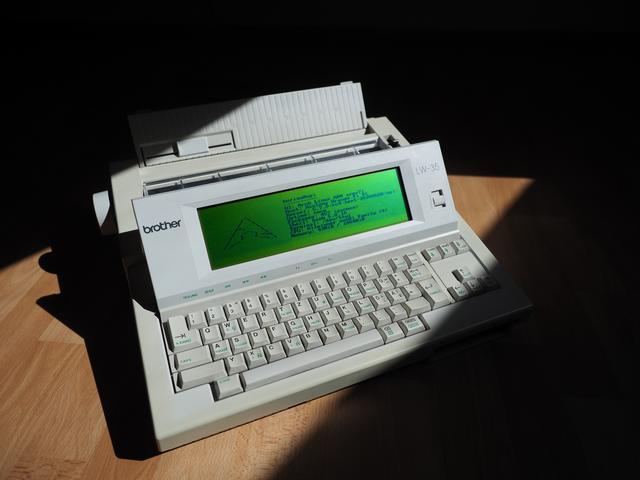
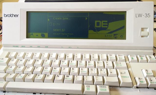
The Orange Pi PC has full mainline Linux support, so pretty much any embedded Linux distribution can be used after the addition of the LW-35-specific drivers. In my case, I went with ArchLinux due to its low memory footprint, ease of modification and, well, personal preference. By the way, and just in case you didn't know already, I use Arch.
Then What Can I Do With It?

The possibilities are endless! You have the entirety of Linux-power at your disposal on this machine now. You want to write a book? Open nano, or vim, or emacs. Want to administer your servers? Open an ssh-session. Want to debug some hardware on your bench, connect it to the serial port and transfer data. Want to browse the web? Open w3m and surf away. Want to watch an ultra-widescreen ASCII movie, go ahead! And for the brave ones, you can even go crazy and launch an X-Server on it!
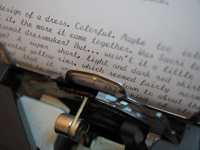
Then, there's the printer of course! While the daisy-wheel printer might not allow graphics or fancy font effects, the results with the fonts that you have available look gorgeous. Just take a look at these prints:
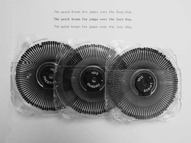
There's even one type face called "Quadro," so I can now legitemately say that I have a Quadro in my machine.
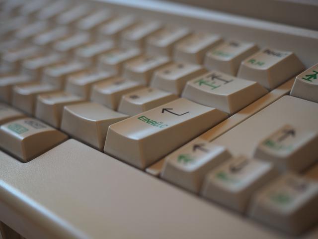
With all that being said, the main use of this machine will be distraction free writing. The original keyboard, despite it being a membrane keyboard at the core, feels great to type on. Each key has its individual spring and stabilizer, giving it a very even feel. And for this use case, the limitations of the device become its strength. It isn't able to really display modern web pages, it isn't able to play games, it can't (realistically) display video. When you sit down at this machine, you have no choice but to do what you came for, and nothing else.
Technical Details
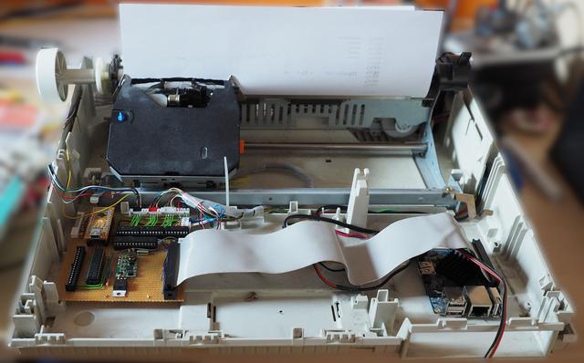
Okay, enough with the sales brochure! Let's talk hardware.
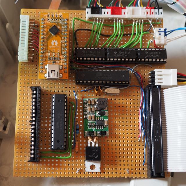
The hardware mainly consists out of two boards, which completely replace the LW-35's original logic board. First, the Orange Pi PC SBC, which provides all hardware needed for the computer part of the system, and second, the I/O board. The I/O board provides the Orange Pi SBC with an interface to the original components of the typewriter: the display, the keyboard, and the printer. Let's first take a look at the overall system architecture, and then go through them one by one in detail.
System Architecture

The display controller is connected to the Allwinner H3 SoC via the high-speed SPI bus, whereas the low-speed peripherals like the keyboard and printer connect via UART. Additionally, a GPIO pin can be used to hard reset the controllers for the keyboard and printer. All low-level communication protocols are application specific, and documented in a wonderful form called source code.
Processing Platform
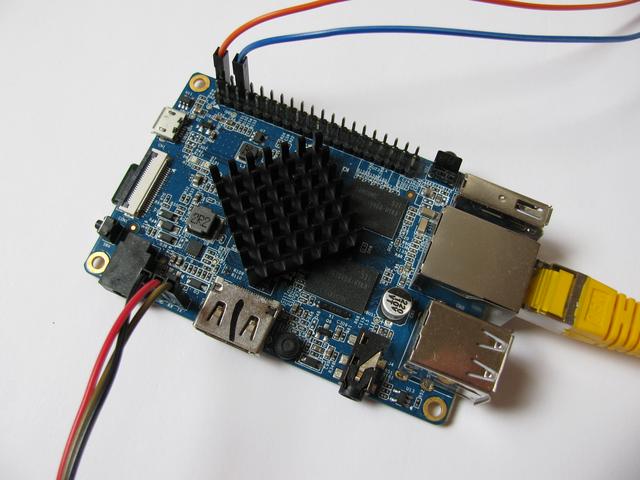
As mentioned earlier, the processing heart is a first generation Xunlong Orange Pi PC [2] single-board computer. It features a Cortex-A7 Quad-core CPU at 1.2 GHz with a Mali400 MP2 GPU. It has 1 GB of RAM and boots off an SDHC memory card. It supports 100 MBit/s networking, and features USB 2.0 for expansion. Both are last-gen protocols, but they are certainly enough for a machine of this type. The board connects to the rest of the hardware via it's I/O expansion header. Theoretically, I could have also gone with a Raspberry Pi. But I mean, come on, look at the two boards side by side: the Orange Pi PC has the CPU at a 45 degree angle. That makes the board at least 20% cooler, so there's no contest as to which board to choose.
The Display
The display is the original screen from the brother LW-35 typewriter. It is a monochrome, 480x128 pixel large LCD with no controller.
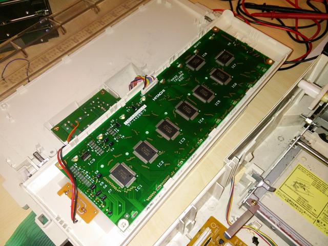
Instead of a controller, it features a set of OKI Semiconductor MSM5299A [3] and MSM5298A [4] LCD driver ICs. This means that we are required to constantly stream the full image data to the display if we want it to display anything. Traditionally, this would be achieved using something like the OKI Semiconductor MSM6255 [5] controller IC, but that interface would then not be directly compatible with the Orange Pi PC again, and it would also require creating a special printed circuit board (PCB) for the purpose, all that besides the pain of sourcing the chip. So, in the end it was better to just create a custom LCD controller from scratch.
This LCD controller was implemented using a field programmable gate array (FPGA) [6]. An FPGA is, similar to a microcontroller, an IC whose functionality can be configured by the designer after manufacturing (hence the name "field programmable"). In contrast to a microcontroller, however, the FPGA will not run instructions on a processor with memory. Instead, an actual digital circuit will be realized inside of the chip. This digital circuit can be defined by the designer in a so called hardware description language (HDL) such as VHDL or Verilog, which is then "converted" into basic logic functions which can then be wired up inside of the chip. If you want to know a little more about the internals of FPGAs, feel free to take a look at my TTL-FPGA [7] project.
FPGAs are well suited for this use case as we need to generate comparatively high-speed waveforms with precise timing. The design implements an SPI addressable memory as frame buffer. This frame buffer is then streamed to the LCD panel through the driver ICs with the refresh rate of the panel. In addition to the raw image data, additional signals are generated to toggle LCD driver voltages in order to avoid burn-in of the cells. To give some numbers, the display refreshes its 61440 pixels at around 130 Hz, which requires a pixel clock of around 2 MHz on the 4-bit parallel interface, and results in a total bandwidth requirement of 8 MBit/s. The SPI bus to the CPU can be run at up to around 10 MHz considering the internal FPGA clock of 96 MHz, although higher speeds become more and sensitive to noise and electro-magnetic interference. In its current implementation, the Orange Pi SBC drives the interface at 2 MHz over the considerably long ribbon cable without any issues. To reduce the load on the CPU, transactions on the SPI bus will only occur if the image has actually changed.
Since FPGAs are not available in dual-in-line (DIL) packages and can therefore not be easily put on a breadboard, a break-out / development board was used. My own Tiny-XO2 [8] was pretty much a perfect fit with just the right amount of I/O and memory.
If you are curious about the reverse engineering effort of the display, take a look at part 1 [9] of the vlog series.
The Keyboard

The keyboard was by far the simplest part. It was just a matter of figuring out which key connects which pair of the control lines. This was quickly done using a high-contrast image of the keyboard matrix and a (virtual) pen. Then, it all that was left was deciding on how to place special keys -- and some normal ones because their spot was taken by some other key like tab -- and writing the software.
At the same time, the keyboard controller has to forward messages from the printer controller as they are in one UART chain with the CPU. Because there are now two types of messages on the bus, a simple packet structure with a single "type" field has been deployed. That way, the keyboard controller only has to make sure to avoid interleaving frames from itself and the printer. The CPU will then later be able to separate which controller sent the message using the "type" field.
For more information, especially about the software implementation of the controller, head on over to part 2 [10] of the vlog series.
The Printer
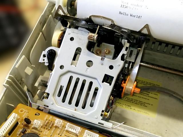
Last, but certainly not least, the printer controller. This was by far the most time consuming part, gifting me with many sleepless nights.
Let me start this section off with a quick explanation of what a daisy wheel printer is, because I suspect that there's many of you who have never heard of this. Modern printers usually work by rasterizing the characters and printing them pixel by pixel. This means that they convert the letter from a path (for example an ellipse for an o) into a set of black and white pixels at the specified font size. These pixels are then individually printed onto the paper at a fixed grid. When this grid is narrow enough, it appears as if a continuous character has been drawn. A daisy wheel printer, on the other hand, has more in common with a conventional mechanical typewriter, where each letter has it's own type hammer with the individual letters milled into the material. Just that the set of hammers is replaced with a single hammer and a smaller rotating disk in front of it, which carries small plates with the characters molded onto them. This has the advantage of a very clean type face, but to change the font, the entire daisy wheel needs to be replaced, which can become quite tedious if there are many different fonts used in a document. The same applies for styles such as bold or italic, although for some things there are workarounds. More about that below. One more note before I move onto the details: These printers don't use ink. Like conventional typewriters, they use ribbons from which the color is transferred to the paper.
To control the printer mechanics, a total of three stepper motors, one DC motor, two solenoids, and one switch needs to be controlled or processed. One stepper motor each is used to control the paperfeed, to move the carriage left and right, and to rotate the daisy wheel. The two solenoids are used to arm the hammer and to arm the change to the correction tape. The DC motor is used to perform the armed actions, i.e. tension and release the hammer mechanism, and switch over to the correction tape, which will effectively move the entire printhead assembly up a few millimeters. The switch can be used to detect whether the carriage has moved to the far left or whether the correction mode is active. All other steps, like moving the ribbon forward with each character, are implemented in the mechanics of the printer.
The hard part about this is that none of it is documented. Everything, from the function of each of the components to the waveforms and electrical properties of the signals to drive them, had to be reverse engineered. Luckily, I still had the original main board available, which helped a lot with the process.
But it's not all about just just figuring out how to drive the hardware. It's also about using it in a smart way. For example, if we went ahead and printed left to right, then went to the beginning of the next line, and printed the second one, we'd effectively be wasting the time it takes to return the printhead to the left side. So why not print both directions? Print the first line left to right, then just move the paper to the next line, reverse the line's content, and print it right to left. Another example would be tricks for formatting. As noted above, any font style should require a new daisy wheel, but some simple changes can be made without. Say we want to print bold text. Turns out we can just print the same character multiple times at the same place. The backlash of the printer assembly will cause the hammer to hit the paper at a slightly different spot each time, creating the impression (pun intended) of a bold letter. If we want to underline some text, we can just print the part once with the normal characters, and then repeat the print, but print underscores (_) instead of the characters.
For more information, look no further than parts 3 [11] and and 4 [12] of the vlog series.
I/O Controller Kernel Driver
I/O controller is a collective term used throughout the repository for the keyboard and printer controller together. This is required as they share the same bus towards the CPU, and therefore the same kernel driver. This kernel driver provides 2 functions to the operating system. First, a keyboard input device, which uses the packet data from the keyboard controller, and second, an interface to send data to the printer.
The printer driver also has to handle initializing the hardware and provide buffering of print data as the AVR can only store about 250 characters in it's buffer. Additionally, this driver is also able to put each AVR into a firmware update mode, which allows to reconfigure the microcontrollers from the running system. And since the toolchain is 100% open source, it's even possible to do the whole development on the device itself.
Vlog 5 [13] documents the final steps and presents all new parts working together for the first time.
Power Supply
The last topic to cover that hasn't been mentioned up until now is the power supply. Originally, the LW-35 came with a single, 8 Volt power supply, which supplied both the "analog" and, through another linear dropper, the digital portion of the circuit. However, by upgrading the old HD64180PR6 8-bit CPU to a modern ARM CPU, the power consumption did go up noticeably. Not by too much -- the whole system still only draws around 4 Watts in idle, with peaks of around 16 Watts when the printer is operating -- but enough to probably cause problems with the fully linear power supply of the original design. And I am not too keen on seeing this thing go full nuclear meltdown on me. So, to tackle this issue, I added a secondary 5 V switch-mode power supply (SMPS) in addition to the existing 8 V supply. The original one now only supplies the motors, solenoids, and the backlight, whereas the new 5 V supply takes care of the Orange Pi PC and the digital portion of the system.
Summary and Review
To summarize, this project turned an old, slowly dying typewriter into a usable machine for convenient distraction free writing once again. It can do many more things now without sacrifying any features, besides maybe the ease of use in more complex scenarios than writing plain text. It is possible to edit directly on a network drive; you can customize your keyboard layout, which btw is super important for someone like me who uses the dvorak-layout on a daily basis; you can listen to music while writing; and much more.
To achieve this, the original electronics have essentially been completely replaced, only leaving the mechanics. The system now runs on a many magnitudes faster CPU, which has more cache than the original system had RAM. All embedded controllers now run 100% open source firmware, which can be customized to your heart's desire.
This upgrade has been incredibly educational as it touched many different disciplines within embedded hardware design:
- Reverse engineering of embedded devices
- FPGAs
- Microcontrollers
- Working with Linux SBCs
- Writing Linux drivers
- Mechanics
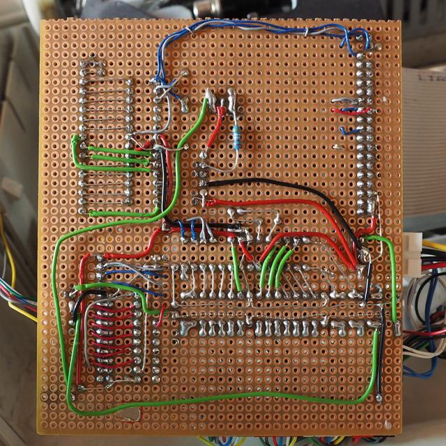
After a project is completed, there's almost always things that one would do differently. And of course, it's no different here. To start off, seeing how complex everything turned out in the end, I'd completely change the hardware architecture of the I/O board. Currently, the AVR handling the printer is already operating at it's limits in regard to pretty much everything. I/Os are used up, you can notice short delays when processing the line buffer, and when enabling debug features, we start to run out of RAM. So, if I knew everything I know now, I'd probably go for a single, larger FPGA to implement everything. It could handle things like driving the stepper motors in hardware, and then make use of a soft core processor (like an OpenRISC or a RISC-V) for handling the communication with the Orange Pi SBC. This integrated hardware design would then also require the design and manufacturing of a proper PCB, but considering the amount of time it took to plan out and optimize the bread board layout for the current implementation, the time would've been worth it.
Another point that should be noted is the quality of the code, especially in regard to the Linux kernel drivers. This was my first time writing Linux drivers and the code quality is according, just refer to this quote from my first vlog of this series: "So after a couple of hours of learning how to write Linux drivers, I got the [...] display driver up and running." That's really how it was. What I'm trying to say is it's bad, don't use it. The firmware / HDL for the keyboard controller and the display controller should be mostly fine though, so please feel free to use it as a refence if you're doing something similar.
If you haven't seen enough of this project yet, make sure to check out the other posts [1] I made about the build process of the device, or jump directly to the YouTube playlist [14].
Alternatively, if you want to get your hands real dirty, here's the link to all the source code written for this project: Git repository [15]
As always, if you have any questions or comments, do not hesitate to contact me via email or some other way listed on my contact page [16].
PS: Hey, you made it! Thanks for reading this post until the end! As a little bonus, here's a fun story involving the typewriter from my days at university. It must've been around 2014. So, one time we got an assignment in our CS class, and we were not allowed to write it on a computer and had to turn it in on a piece of paper. Probably to prevent one person from actually doing the assignment and everyone else just copying it -- not like that doesn't happen even with that restriction in place. Anyways, I don't like writing by hand, so guess what I did? Right, I grabbed the old, back then fully original, LW-35 and typed my homework on that, printed it, and turned it in. He had no chance but to accept it. It wasn't written by hand, sure, but that wasn't what he had requested, he only said he wants it not to be done on a PC. Yeah... fun times :)
Gallery
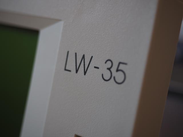
Now, to conclude this mammoth of a project once and for all, here's some more photos.



Embedded content has been disabled to protect your privacy.
or click here to allow them permanently,
or click here to watch the video on YouTube:
https://www.youtube.com/watch?v=Braqmqbj7Qk
Please note that, by enabling this video, data is transferred
to YouTube LLC, and is subject to their privacy policy.Embedded content has been disabled to protect your privacy.
or click here to allow them permanently,
or click here to watch the video on YouTube:
https://www.youtube.com/watch?v=b_vZhPZ220U
Please note that, by enabling this video, data is transferred
to YouTube LLC, and is subject to their privacy policy.
Also be sure to check out the vlog series [1] to see all features in action.
Sources:
[1]: https://notsyncing.net/?p=blog&t=lw35
[2]: http://www.orangepi.org/orangepipc/
[3]: http://pdf.datasheetcatalog.com/datasheet/oki/MSM5299AGS-K.pdf
[4]: http://pdf.datasheetcatalog.com/datasheet/oki/MSM5298A.pdf
[5]: http://pdf.datasheetcatalog.com/datasheet/oki/MSM6255.pdf
[6]: https://en.wikipedia.org/wiki/Field-programmable_gate_array
[7]: https://notsyncing.net/?p=blog&b=2019.ttl-fpga
[8]: https://notsyncing.net/?p=blog&b=2017.tiny-xo2
[9]: https://notsyncing.net/?p=blog&b=2018.lw35-vlog-1
[10]: https://notsyncing.net/?p=blog&b=2018.lw35-vlog-2
[11]: https://notsyncing.net/?p=blog&b=2018.lw35-vlog-3
[12]: https://notsyncing.net/?p=blog&b=2018.lw35-vlog-4
[13]: https://notsyncing.net/?p=blog&b=2018.lw35-vlog-5
[14]: https://www.youtube.com/playlist?list=PLtys0X8RdKnm_d-7DvOF2YU0SbDM3cjJB
[15]: https://git.notsyncing.net/electronics/lw35-upgrade
[16]: https://notsyncing.net/?p=contact
