DIY power amplifier | | Thursday, December 10th 2015, 15:55 |
In one of my older videos, I tested an audio power amplifier circuit by Douglas Self [1] on a breadboard.
Embedded content has been disabled to protect your privacy.
or click here to allow them permanently,
or click here to watch the video on YouTube:
https://www.youtube.com/watch?v=La5aWvgG5GM
Please note that, by enabling this video, data is transferred
to YouTube LLC, and is subject to their privacy policy.
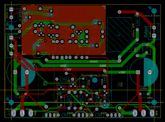
After that evaluation showed how great the design really is, I decided to create a real PCB design for it so I can actually use this as one of my daily use amps.
The entire project, designed using KiCad, is available over in my git repository [2]. KiCad [3] is free and open source software, so just download and install it to open the project.

Also note that the component designators differ between my schematic/layout and the ones on the original schematic by Douglas Self. I also added an additional resistor (Rtodo) as I saw excessive current through the nearby components when clipping.
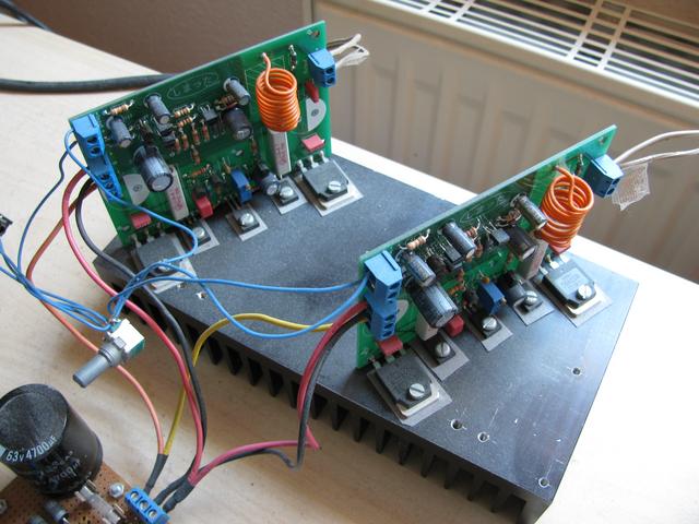
Sadly, I never got around to making a case for it, so it just sits on my bench as is. Here's a dusty photo of how it turned out:

Should I ever finish the project in the future, I might make another video about it. If you have any questions until then, don't hesitate to contact me via email.
Sources:
[1]: http://www.douglas-self.com/ampins/dipa/dipa.htm
[2]: https://git.notsyncing.net/electronics/poweramp-dself
[3]: http://kicad-pcb.org/
